Why Use Fibre Optic Cable?
Fibre Optic is a technology that uses glass (or
plastic) threads (fibres) to transmit data. A fibre
optic cable consists of a bundle of glass threads, each
of which is capable of transmitting messages modulated
onto light waves. There many options available today to
transmit Video Voice and Data. You could use Cat 5
cable, Radio, Co-Ax cable but none are as secure as
Fibre.
Fibre optic cable is used as a replacement to cable
systems and has several advantages over copper cable.
Immune to interference: Any form of EMI or EMC
interference does not affect Fibre optic cabling. It’s
unique characteristics make it immune to cross-talk,
radio and electrical disturbances, allowing you to lay
it where you need it, without having to worry about the
proximity to electrical systems.
Lightning Protection: A Big advantage of fibre is
that it is non conductive and thus isolates the remote
equipment from the local equipment and therefore
protects the equipment from longitudinal induced
lightning currents.
Security: Fibre is secure as it is not possible
to tap into the fibre along a route. Fibre can carry a
large amount of data in digital form with no
deterioration of signal. Optical losses are far less
than losses that could be experienced in copper cable or
on radio links. Thus making it ideal over longer
distances. Fibre is also suitable for shorter
distances from 100meter upwards to 100km and more by
adding additional equipment.
Weight: a Great advantage of fibre is its
lightweight construction. This is especially useful when
fibre is used down mineshafts or in large buildings, on
cranes. Cost savings on transport and handling is a
great advantage.
Fibre cable construction
Fibre Optic Cables were introduced into South Africa
around the late 70’s. ATC set up a manufacturing plant
to produce the product locally. There are many
differently constructed cables available. Be sure to
select one with the ruggedness suitable for the
application.
In general a Fibre optic cable
consists of a rugged plastic outer Sheath some with an
additional inner Tube supported with Kevlar for strength
and then with a multiple individual single core fibres
coated with a with 125 micron clading. Each fibre can
measure 50 micron for multimode applications and 8
micron for single mode applications. These cables are
suitable for use on mines, industrial sites, Airports
and long distance communication. Application for CCTV,
IP Networks and Access control are found in shopping
centers factories and the like. Lately the advantages of
fibre are realized in the ordinary domestic areas for
intercoms security video monitoring.
 |
(POF): Another
form of fibre called Plastic optical fibre (or
Polymer optical fibre) an optical fibre which is
made out of plastic. These fibres are suitable
for lower data rates and shorter distances.
Since the late 1990s however, much
higher-performance POF based fibres has begun to
appear in the marketplace. This lends itself to
be looked at again in the light of the
increasing domestic market. This fibre has a
much larger core diameter as much as 1mm and
light is transmitted through the complete core
of the fibre. POF has been called the “consumer”
optical fibre because the fibre and associated
optical links, connectors, and installation are
all inexpensive. |
| Fibre cable
application |
|
|
 |
Fibre cables
can be laid underground, or strapped to existing
infrastructure and are even used down
mineshafts.
Connection and joining of fibre cable is a
precision job done with special tools
needed and thus has to be done by the installer
who will terminate the cable on a patch panel.
From there a patch lead is used that connect to
the equipment. These patch leads come in single
or duplex fibre almost like twin flex with the
connecters already fitted and can be connected
by the user.
Plastic Optical Fibre is more suited in the
domestic environment as it is easier to install
and to terminate a crimping pliers with a
cutting and polishing kit can be purchased at a
reasonable cost. It is more suited for domestic
applications as the installation distances of a
link rarely exceed 100m. |
|
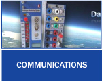
Fibre-optics can be seen as a
replacement for copper wire systems for
communication and signal transmission. It can
span long distances and provide the backbone for
many network systems. Other system users include
television services, network on university
campuses, between office buildings, industrial
plants, and electric utility companies. Lately
we see the new telecoms providers as well as
Telkom installing large infrastructure to carry
fibre networks all over the country. These
networks have a special fibre deployment method
called blown fibre. This is when the fibre cores
are
blown into the pipes as needed. |
How does it work
Think of a fibre cable in terms of
very long cardboard tube that is coated with a mirror on
the inside. If you shine a flashlight in one end you can
see light come out at the far end - even if it’s been
bent around a corner because the light is reflected by
the mirror finish inside the tube.
Light pulses move easily down the
fibre-optic line because of a principle known as total
internal reflection. This principle of total internal
reflection states that when the angle of incidence
exceeds a critical value, light cannot get out of the
glass; instead, the light bounces back in. When this
principle is applied to the construction of the fibre-optic
strand, it is possible to transmit information down
fibre lines in the form of light pulses.
The core must have a very clear and
pure material for the light or in most cases near
infrared light (850nm, 1300nm and 1500nm) is used. The
core can be Plastic (used for very short
distances) but most are made from glass. Glass optical
fibre is almost always made from pure silica, but some
other materials, such as fluorozirconate,
fluoroaluminate, and chalcogenide glasses, are used for
longer-wavelength infrared applications. Fibre optic
cable functions as a “light guide,” guiding the
light introduced at one end of the cable through to the
other end.
The light source can either be a
light-emitting diode (LED) or a laser. The light source
is pulsed on and off, and a lightsensitive receiver on
the other end of the cable converts the pulses back into
the digital ones and zeros of the original signal. Even
laser light shining through a fibre optic cable is
subject to loss of strength, primarily through
dispersion and scattering of the light, within the cable
itself. The faster the laser fluctuates, the greater the
risk of dispersion. Light strengtheners, called
repeaters, may be necessary to refresh the signal in
certain applications.
While fibre optic cable itself has
become cheaper over time - a equivalent length of copper
cable cost less per meter but does not carry have the
same data capacity.
In order to use fibre optic cable we
need special terminating devices. To produce the light
use is made of LED technology for shorter
distances and lasers for longer distances and higher
data rates. On the receive side light sensitive devices
that detect the light and convert it into an electrical
signal are used. These devices come in various shapes
and sizes and with different connecters.
Mainly 3 Fibre types are used:
Single mode fibre has the best performance
characteristics and the highest data throughput see the
fibre specs. Because of the smaller diameter fibre used
the cost of the connectors, installation terminating
equipment etc. all make the installation more expensive.
Multimode fibre is used for analog
video transmission and digital transmitter and receiver
units making it more cost effective. Transmission range
is reduced to 3km for 850nm optics and 12km for 1300nm
optics the later being more expensive to terminate but
still suitable for analog video transmission.
Then POF work at much shorter
distances within the 100m range but terminating the
cables are easier thus reducing installation costs but
also with reduced bandwidth. However Siemens has now
developed a new modulation method that enable bandwidths
up to the Gigibit range however this equipment will be
expensive for the near future.
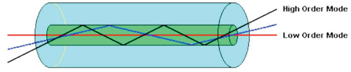
Multi-mode
Fibre has a large core, up to (50 microns in
diameter). As a result, some of the light rays that make
up the digital pulse may travel a direct route,
whereas others zigzag as they bounce off the cladding.
These alternative pathways cause the different groupings
of light rays, referred to as modes, to arrive
separately at a receiving point. The pulse, an aggregate
of different modes, begins to spread out, losing its
well-defined shape. The need to leave spacing between
pulses to prevent overlapping limits bandwidth, that is,
the amount of information that can be sent.
Consequently, this type of fibre is best suited for
transmission over shorter distances, up to 12km.
Bandwidth approaches 500Mb/km the colour of multi mode
patch cord is usually Orange.
Single-mode
Fibre has a narrow core (8 microns or less), and the
index of refraction between the core and the cladding
changes less than it does for multi-mode fibre. Light
thus travels parallel to the axis, creating very low
pulse dispersion. Bandwidth in the Gigabit range. The
color of single mode patch cords are usually Yellow.
Standalone
Entity is something that has no dependencies; it can
“stand alone”. Referred to as a table top unit or peace
of equipment. These units can be mounted in pole mounted
boxes with separate or built in power supplies. Rack
mount - is a standardized frame or enclosure for
mounting multiple equipment modules. Each module has a
front panel that is 19” wide, including edges or ears
that protrude on each side which allow the module to be
fastened to the rack frame with screws.
Security quality
There is no specification for the quality required
for security therefore we often see video recordings
where the image is of a crime perpetrator is not
recognisable making the video useless. It is important
to note that the camera position and degree of zoom can
make all the difference to an installation. If you want
to see the bird in a tree then it is necessary to have
the whole tree in the picture and not the full
landscape. The position of the sun is just as important.
Sun rays reflecting into the camera lens can totally
blank out a picture making it useless.
Broadcast quality
(http://encyclopedia2.thefreedictionary.com/broadcast+quality+video)
This is usually referred to as picture quality suitable
for broadcast. We are used to the normal analogue TV
picture quality and compare all other video pictures to
this. Lately we have DSTV and DVD quality which is a
compressed form of video with excellent results. This
compression is also used in Digital Video Recorders
Normally called MPEG-4 or H.264/MPEG-4 . To obtain
similar quality in a security system we have to use good
quality cameras with at least 640 lines per frame. It is
essential to eliminate long lengths of copper wire as
this reduces the picture quality. Analogue video on
fibre over distances up to 2km is acceptable for this
quality, however digital video on fibre will give a
better result and there will be no degradation of signal
quality or any noise due to attenuation and can be
transmitted over 24km with little effort. The use of IP
based systems can be considered on application. IP
systems rarely provide real time video which could be a
problem in some applications, however higher resolution
cameras are available.
H.264 is perhaps best known as being
one of the codec standards for Blu-ray Discs; all Blu-ray
players must be able to decode H.264. It is also widely
used by streaming internet sources, such as videos from
‘Vimeo’, YouTube and the iTunes Store, web software such
as the Adobe Flash Player and Microsoft Silverlight,
broadcast services for DVB and SBTVD, direct-broadcast
satellite television services, cable television
services, and real-time videoconferencing.
Analog
The most used broadcast option and also the most widely
available. Units are easily obtainable and very cost
effective. ADD offers from 1 to 3 channel equipment in
this category for fixed and dome (PTZ) cameras. Both
multi-mode and single-mode are available. Card frames
can handle up to 30 channels on a 3U level
Analog Circuit
A circuit or device having an output that is
proportional to the input; “analogue device”; “linear
amplifier”. An analogue video signal will instantly
modulate the light luminance (brightness) in a
fibre as the picture intensity changes this is done up
to 6 million times a second capturing the chrominance (colour)
and all the picture detail.
Analogue signals
Signals that are continually changing, as opposed to
being digitally encoded.
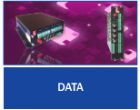
Digital
Signals encoded into discrete bits. Multiplexers fall
into this category. These are units that can transmit
and receive multiple video, audio and data channels on 1
fibre. Mostly used when an existing site wants to add
more cameras and only has a limited amount of already
installed fibre left. ADD offers 4, 8, 16 and 32 channel
units.
Radio Broadcast
A common method of broadcasting video but can be
limited in area. Very dependent on the layout and
geography of an area. A further consideration is that
only a limited amount of channels are available for use
and an area (i.e. mine) can quickly become saturated.
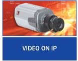
Lan Based Broadcasting
Also known as IP video Has become very popular
because of its ease of use and familiarity of the
technology to people. Many sites are Lan based and a
myriad of cameras, transmitters, receivers and
software options are available in today’s market. This
has a tendency to limit itself as bandwidth quickly gets
exhausted, especially if high quality recordings are
called for. Dedicated lan networks are recommended.
Din Rail
Is a standardised 35mm wide metal rail with
hat-shaped cross section. It is widely used for mounting
circuit breakers and industrial control equipment inside
equipment racks. It is also used to house fibre
interface units, power supplies, video transmitters etc.
Speed
Fibre optic networks can operate at high speeds - up
into the gigabits/second.
Bandwidth
Large data carrying capacity normally expressed as
data throughput in bits per second. Also referred to as
the range of signal frequencies or bit rate within which
a fibre optic component, link or network will operate.
EMI Electromagnetic interference
Also called radio frequency interference or RFI, is
a disturbance that affects an electrical circuit due to
either electromagnetic induction or electromagnetic
radiation emitted from an external source. The
disturbance may interrupt, obstruct, or otherwise
degrade or limit the effective performance of the
circuit. The source may be any object, artificial or
natural, that carries rapidly changing electrical
currents, such as an electrical circuit or cables.
Lightning is the biggest contributor to this
interference.
Module
Is a general systems concept, typically defined as a
continuum describing the degree to which a system’s
components may be separated and recombined. It refers to
both the tightness of coupling between components, and
the degree to which the “rules” of the system
architecture enable (or prohibit) the mixing and
matching of components.
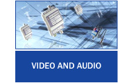
Video and Audio
Our video products deliver crisp, clear, full-speed
streaming video over fibre-optic. ADD’s video products
have a proven reliability record with more than 10,000
links installed in the field. Available in single and
multi-channel configurations. Audio and contact closure
cards provide total CCTV / security solutions.
Access control
Is a system which enables an authority to control
access to areas and resources in a given physical
facility or computer-based information system. An access
control system, within the field of physical security,
is generally seen as the second layer in the security of
a physical structure. It can be a gate controlled by an
electronic lock by which access is gained into a
security area.
Audio
Is simply that part of a signal that one can hear
once it is converted into sound waves. The
specifications normally go beyond the normal audio
range. A normal person can hear sound waves from
20cycles per second to approximately 7000cycles per
second. The audio specifications for HIFI equipment
specify signals from 10 – 20000cycles. As an interest
the normal POTS telephone has a specification of 200 to
3400cycles per second.
Digital video
In relation to fibre digital video as opposed to
analogue video is the conversion of the analogue signal
into a data stream and sending light pulses down the
fibre. These pulses are recovered on the receive side as
ones and zeros eliminating any interference along the
way. Whereas a analogue signal can become noisy as the
distance increases the digital signal is recovered
without noise. Digital video uses a high data rate to
send video signals across fibre this lends itself to
also include audio and data signals on the same fibre.
Digital Data
Is to refer to more than one concept. It can refer
to discrete-time signals that have a discrete number of
levels, for example a sampled and quantified analogue
signal, or to the continuous-time waveform signals in a
digital system, representing a bit-stream. In the first
case, a signal that is generated by means of a digital
modulation method, which is considered as, converted to
an analogue signal, while it is considered as a digital
signal in the second case.
Power Supply Unit
Is a device that supplies electrical energy to one
or more electric loads. The term is most commonly
applied to devices that convert one form of electrical
energy to another, though it may also refer to devices
that convert another form of energy (e.g., mechanical,
chemical, solar) to electrical energy. A regulated power
supply is one that controls the output voltage or
current to a specific value; the controlled value is
held nearly constant despite variations in either load
current or the voltage supplied by the power
supply’s energy source.
Video Recorder
A digital video recorder (DVR) or personal video
recorder (PVR) is a consumer electronics device or
application software that records video in a digital
format to a disk drive, USB flash drive, SD memory card
or other local or networked mass storage device. The
term includes set-top boxes with recording facility,
portable media players (PMP) with recording facility,
recorders (PMR as camcorders that record onto memory
cards) and software for personal computers which enables
video capture and playback to and from disk. A
television set with built-in digital video-recording
facilities was introduced by LG in 2007 followed by
other manufacturers.
Profibus
(Process Field Bus) is a standard for field bus
communication in automation technology and was first
promoted (1989) by BMBF (German department of education
and research). It should not be confused with the
PROFINET standard for Industrial Ethernet. Data rates of
up to 500kb/s are standard for this communication
system. This bus system is normally driven by RS485
interface units.
RS232
In telecommunications, (Recommended Standard 232) is a
standard for serial binary single-ended data and control
signals connecting between a DTE (Data Terminal
Equipment) and a DCE (Data Communication Equipment). It
is commonly used in computer serial ports. The standard
defines the electrical characteristics and timing
of signals, the meaning of signals, and the physical
size and pin out of connectors. This standard is no
longer supported by your normal PC. The USB port
has taken over most of its function.
RS485
lso known as TIA/EIA-485 or RS-485, is a standard
defining the electrical characteristics of drivers and
receivers for use in balanced digital multipoint
systems. The standard is published by the ANSI
Telecommunications Industry Association/Electronic
Industries Alliance (TIA/EIA). Digital communications
networks implementing the EIA-485 standard can be used
effectively over long distances (up to 1 km) and in
electrically noisy environments. Multiple receivers may
be connected to such a network in a linear, multi-drop
configuration. These characteristics make such networks
useful in industrial environments and similar
applications. Only two wires are needed to carry the
this signal and the protocol operates in a half duplex
mode. Like talking to your mother in Law. When she
speaks you shut up.
RS422
Is a common short form and former official title of
American National Standards Institute (ANSI) standard
ANSI/TIA/EIA-422-B and its international equivalent ITU-T
Recommendation T-REC-V.11, also known as X.27. These
technical standards specify the electrical
characteristics of the balanced voltage digital
interface circuit. RS-422 provides for data
transmission, using balanced or differential signalling,
with unidirectional/non-reversible, terminated or
non-terminated transmission lines, point to point, or
multi-drop. In contrast to EIA-485 (which is multi-point
instead of multi-drop), EIA-422/V.11 does not allow
multiple drivers but only multiple receivers. This is a
4 wire system that allow but rarely used data
communication in both directions at the same time.
Data circuit
In telecommunication, is the transmission media and
the intervening equipment used for the transfer of data
between data terminal equipments (DTEs).
X.21
Sometimes referred to as X21, is an interface
specification for differential communications introduced
in the mid 1970s by the ITU-T. X.21 was first introduced
as a means to provide a digital signalling interface for
telecommunications between carriers and customers’
equipment. This includes specifications for DTE/DCE
physical interface elements, alignment of call control
characters and error checking, elements of the call
control phase for circuit switching services, and test
loops. This communication is similar to RS422 with the
addition of a sync clock signal pair added to the
connector. All data is then synced to the clock signal.
MUX a multiplexer or MUX
Occasionally the terms muldex or muldem are also
found for a combination multiplexer-de-multiplexer, is a
device that performs multiplexing; it selects one of
many analogue or digital input signals and forwards the
selected input into a single data line. A multiplexer of
2n inputs has n select lines, which are used to select
which input line to send to the output.
An electronic multiplexer makes it
possible for several signals to share one device or
resource, for example one A/D converter or one
communication line, instead of having one device per
input signal.
On the other end, a demultiplexer (or
demux) is a device taking a single input signal and
selecting one of many data-output-lines, which is
connected to the single input. A multiplexer is often
used with a complementary demultiplexer on the receiving
end.
An electronic multiplexer can be
considered as a multiple-input, single-output switch,
and a demultiplexer as a single-input, multiple-output
switch. The schematic symbol for a multiplexer is an
isosceles trapezoid with the longer parallel side
containing the input pins and the short parallel side
containing the output pin. The schematic on the right
shows a 2-to-1 multiplexer on the left and an equivalent
switch on the right. The sel wire connects the desired
input to the output.
In telecommunications, a multiplexer is a device that
combines several input information signals into one
output signal, which carries several communication
channels, by means of some multiplex technique. A
demultiplexer is in this context a device taking a
single input signal that carries many channels and
separates those over multiple output signals.
Telephone Circuit
Is any line, conductor, or other conduit by which
information is transmitted. A dedicated circuit, private
circuit, or leased line is a line that is dedicated to
only one use. Originally, this was analog, and was often
used by radio stations as a studio/transmitter link (STL)
or remote pickup unit (RPU) for their audio, sometimes
as a backup to other means. Later lines were digital,
and used for private corporate data networks.
The opposite of a dedicated circuit is a switched
circuit, which can be connected to different paths. A
POTS or ISDN telephone line is a switched circuit,
because it can connect to any other telephone number.
On digital lines, a virtual circuit
can be created to serve either purpose, while sharing a
single physical circuit.
Video Server
Is a computer based device (also called a ‘host’)
dedicated to recording and delivering video.
Video Decoder
is a device or software that enables video
compression and/or decompression for digital video. The
compression usually employs lossy data compression.
Historically, video was stored as an analogue signal on
magnetic tape. Around the time when the compact disc
entered the market as a digital-format replacement for
analogue audio, it became feasible to also begin storing
and using video in digital form, and a variety of such
technologies began to emerge.
Fiber media converters
Are simple networking devices that make it possible
to connect two dissimilar media types such as twisted
pair with fiber optic cabling. They were introduced to
the industry nearly two decades ago, and are important
in interconnecting fiber optic cabling-based systems
with existing copper-based, structured cabling systems.
They are also used in MAN access and data transport
services to enterprise customers.
Patch cable
Is an electrical or optical cable, used to connect
(“patch-in”) one electronic or optical device to another
for routing. Devices of different types (ie: a switch
connected to a computer, or switch to router) are
connected with patch cords. Patch cords are usually
produced in many different colours so as to be easily
distinguishable, and are relatively short, perhaps no
longer than two metres. Types of patch cords include
microphone cables, headphone extension cables, XLR
connector, RCA connector and ¼” TRS connector cables (as
well as modular Ethernet cables), and thicker, hose-like
cords (snake cable) used to carry video or amplified
signals. However, patch cords typically only refer to
those short ones used with patch panels. In optical
systems these patch cords come in single mode (Yellow
Colour) or multimode (orange Colour).
Attenuator electronic
Is normally a non active electronic device that
reduces the amplitude or power of a signal without
appreciably distorting its waveform.
An attenuator is effectively the
opposite of an amplifier, though the two work by
different methods. While an amplifier provides gain, an
attenuator provides loss, or gain less than 1.
Attenuators are usually passive
devices made from simple voltage divider networks. Optic
attenuators are devices that plug in series with a patch
cord or panel to reduce to optic light level. It is
necessary where receive equipment is installed at a
short distance from the transmitter and a overdrive
condition occurs. This is usually resolved in the
planning phase of an installation.
Attenuator Fibre
A device that reduces signal power in a fibre optic
link by inducing loss.
Attenuation in a fibre cable
The reduction in optical power as it passes along a
fibre, usually expressed in decibels (dB). See optical
loss. Various fibre types will have a different
attenuation. See the fibre loss table. Can also be
described as cable loss.
Attenuation Coefficient
Characteristic of the attenuation of an optical
fibre cable per unit length, in dB/km.
Patch Panel
Is a panel, typically rack mounted, that houses
cable connections. One typically shorter patch cable
will plug into the front side, whereas the back holds
the connection of a much longer and more permanent
cable. The assembly of hardware is arranged so that a
number of circuits, usually of the same or similar type,
appear on jacks for monitoring, interconnecting, and
testing circuits in a convenient, flexible manner. This
is suitable for optic cables where bulkheads are used in
the patch panel and the patch cords can easily connect
to the front of the panel.
Monitoring System
In systems engineering is a process within a
distributed system for collecting and storing state
data.
Absorption
That portion of fibre optic attenuation resulting of
conversion of optical power to heat.
Average power
The average signal strength over time of a modulated
signal. It is important to maintain a constant average
power of a signal in order to prevent fluctuations in
compensation of optic receive power in the receiver
circuitry.
Return loss back reflection,
optical
Light reflected from the cleaved or polished end of
a Fibre caused by the difference of refractive indices
of air and glass. Typically 4% of the incident light.
Expressed in dB relative to incident power.
Backscattering
The scattering of light in a fibre back toward the
source, used to make OTDR measurements. This is normally
caused by poor joints, sharp corners or mismatched
connectors in the cable
Bending loss, micro-bending loss
Loss in fibre caused by stress on the fibre bent
around a restrictive radius.
Bit-error rate (BER)
The fraction of data bits transmitted that are
received in error. The acceptable BER of a data link is
normally specified using a communication standard and
can be 1 in 10 power -9 bits. Tests normally run clear
on fibre.
Bit
An electrical or optical pulse that carries 2 states
of information.
Buffer
a device used to temporary store erratic data to
allow a receiver to clock it out at a constant rate.
Optic Cable
One or more fibres enclosed in protective coverings
and strength members.
Cable Plant, Fibre Optic
The combination of fibre optic cable sections,
connectors and splices forming the optical path between
two terminal devices.
Chromatic dispersion
The temporal spreading of a pulse in an optical
waveguide caused by the wavelength dependence of the
velocities of light.
Cladding
The lower refractive index optical coating over the
core of the fibre that “traps” light into the core.
Optic Connector
A device that provides for a demountable connection
between two fibres or a fibre and an active device and
provides protection for the fibre.
Core
The centre of the optical fibre through which light
is transmitted.
Coupler
An optical device that splits or combines light from
more than one Fibre.
Cutback method
A technique for measuring the loss of bare fibre by
measuring the optical power transmitted through a long
length then cutting back to the source and measuring the
initial coupled power.
Cutoff wavelength
The wavelength beyond which single-mode Fibre only
supports one mode of propagation.
dBm
Optical power referenced to 1 milliwatt. 0dBm = 1
milliwatt
Decibel (dB)
A unit of measurement of power which indicates
relative power on a logarithmic scale, sometimes called
dBr. dB=10 log ( power ratio), dBv = 20Log (Voltage
Ratio)
Optic Detector
A photodiode that converts optical signals to
electrical signals.
Dispersion
The temporal spreading of a pulse in an optical
waveguide. May be caused by modal or chromatic effects.
EDFA
Erbium-doped Fibre amplifier, an all optical
amplifier for 1550 nm SM transmission systems.
Edge-emitting diode (E-LED)
A LED that emits from the edge of the semiconductor
chip, producing higher power and narrower spectral
width.
End finish
The quality of the end surface of a fibre prepared
for splicing or terminated in a connector.
Equilibrium modal distribution (EMD)
Steady state modal distribution in multimode Fibre,
achieved some distance from the source, where the
relative power in the modes becomes stable with
increasing distance.
ESCON
IBM standard for connecting peripherals to a
computer over fibre optics. Acronym for Enterprise
System Connection.
Excess loss
The amount of light lost in a coupler, beyond that
inherent in the splitting to multiple output fibres.
Fibre Amplifier
An all optical amplifier using erbium or other doped
fibres and pump lasers to increase signal output power
without electronic conversion.
FDDI
Fibre Distributed Data Interface, 100 Mb/s ring
architecture data network.
Ferrule
A precision tube which holds a Fibre for alignment
for interconnection or termination. A ferrule may be
part of a connector or mechanical splice.
Fibre tracer
An instrument that couples visible light into the
Fibre to allow visual checking of continuity and tracing
for correct connections.
Fibre identifier
A device that clamps onto a Fibre and couples light
from the fibre by bending, to identify the fibre and
detect high speed traffic of an operating link or a 2
kHz tone injected by a test source.
Fibre optics
Light transmission through flexible transmissive
fibres for communications or lighting.
FO
Common abbreviation for “Fibre optic.”
Optical Loss
The amount of optical power lost as light is
transmitted through Fibre, splices, couplers, etc.
Optical return loss, back
reflection
Light reflected from the cleaved or polished end of
a Fibre caused by the difference of refractive indices
of air and glass. Typically 4% of the incident light.
Expressed in dB relative to incident power.
Fusion splicer
An instrument that splices fibres by fusing or
welding them, typically by electrical arc.
Graded index (GI)
A type of multimode fibre which used a graded
profile of refractive index in the core material to
correct for dispersion.
Index profile
The refractive index of a fibre as a function of
cross section.
Insertion loss
The loss caused by the insertion of a component such
as a splice or connector in an optical Fibre.
Jacket
The protective outer coating of the cable.
Jumper cable
A short single Fibre cable with connectors on both
ends used for interconnecting other cables or testing.
Laser diode, ILD
A semiconductor device that emits high powered,
coherent light when stimulated by an electrical current.
Used in transmitters for singlemode Fibre links.
Launch cable
A known good Fibre optic jumper cable attached to a
source and calibrated for output power used as a
reference cable for loss testing. This cable must be
made of Fibre and connectors of a matching type to the
cables to be tested.
Light-emitting diode, LED
A semiconductor device that emits light when
stimulated by an electrical current. Used in
transmitters for multimode Fibre links.
Fibre optic Link
A combination of transmitter, receiver and Fibre
optic cable connecting them capable of transmitting
data. May be Analogue or digital.
Long wavelength
A commonly used term for light in the 1300 and 1550
nm ranges.
Loss budget
The amount of power lost in the link. Often used in
terms of the maximum amount of loss that can be
tolerated by a given link.
Margin
The additional amount of loss that can be tolerated
in a link after the transmitter and receiver
specifications have been taken into consideration. One
would normally require 33% safe margin.
Mechanical splice
A semi-permanent connection between two fibres made
with an alignment device and index matching fluid or
adhesive.
Micron (μm)
A unit of measure, 10-6 m, used to measure the core
of a fibre.
Microscope
Used in Fibre optic inspection. A microscope used to
inspect the end surface of a connector for flaws or
contamination or a fibre for cleave quality.
Mode
A single electromagnetic field pattern that travels
in Fibre. Mode field diameter: A measure of the core
size in single mode fibre. Mode filter: A device that
removes optical power in higher order modes in fibre.
Mode scrambler: A device that mixes optical power in
Fibre to achieve equal power distribution in all modes.
Mode stripper: A device that removes light in the
cladding of an optical fibre. Modal dispersion: The
temporal spreading of a pulse in an optical waveguide
caused by modal effects.
Nanometer (nm)
A unit of measure , 10-9 m, used to measure the
wavelength of light.
Network
A system of cables, hardware and equipment used for
communications.
Numerical aperture (NA)
A measure of the light acceptance angle of the
Fibre.
Optical amplifier
A device that amplifies light without converting it
to an electrical signal.
Optical Fibre
An optical waveguide, comprised of a light carrying
core and cladding which traps light in the core.
Optical loss test set (OLTS)
An measurement instrument for optical loss that
includes both a meter and source.
Optical power
The amount of radiant energy per unit time,
expressed in linear units of Watts or on a logarithmic
scale, in dBm (where 0 dB = 1 mW) or dB* (where 0 dB*=1
microwatt).
Optical switch
A device that routes an optical signal from one or
more input ports to one or more output ports.
Optical time domain reflectometer
(OTDR) An instruments that used backscattered light
to find faults in optical fibre and infer loss.
Overfilled launch
A condition for launching light into the fibre where
the incoming light has a spot size and NA larger than
accepted by the fibre, filling all modes in the Fibre.
Photodiode
A semiconductor that converts light to an electrical
signal, used in Fibre optic receivers.
Pigtail
A short length of fibre attached to a fibre optic
component such as a laser or coupler.
Plastic optical Fibre (POF)
An optical fibre made of plastic.
Plastic-clad silica (PCS) Fibre
A fibre made with a glass core and plastic cladding.
Power budget
The difference (in dB) between the transmitted
optical power (in dBm) and the receiver sensitivity (in
dBm).
Power meter, Fibre optic
An instrument that measures optical power emanating
form the end of a fibre.
Preform
The large diameter glass rod from which fibre is
drawn.
Receive cable
A known good fibre optic jumper cable attached to a
power meter used as a reference cable for loss testing.
This cable must be made of fibre and connectors of a
matching type to the cables to be tested.
Receiver
A device containing a photodiode and signal
conditioning circuitry that converts light to an
electrical signal in fibre optic links.
Refractive index
A property of optical materials that relates to the
velocity of light in the material.
Repeater, regenerator
A device that receives a fibre optic signal and
regenerates it for retransmission, used in very long
fibre optic links.
Scattering
The change of direction of light after striking
small particles that causes loss in optical fibres.
Short wavelength
A commonly used term for light in the 665, 790, and
850 nm ranges.
Source
A laser diode or LED used to inject an optical
signal into Fibre.
Splice (fusion or mechanical)
A device that provides for a connection between two
fibres, typically intended to be permanent.
Splitting ratio
The distribution of power among the output fibres of
a coupler.
Steady state modal distribution
Equilibrium modal distribution (EMD) in multimode
Fibre, achieved some distance from the source, where the
relative power in the modes becomes stable with
increasing distance.
Step index Fibre
A multimode fibre where the core is all the same
index of refraction.
Surface emitter LED
A LED that emits light perpendicular to the
semiconductor chip. Most LEDs used in data
communications are surface emitters.
Talkset, Fibre optic
A communication device that allows conversation over
unused fibres.
Termination
Preparation of the end of a fibre to allow
connection to another fibre or an active device,
sometimes also called “connectorisation”.
Test cable
A short single fibre jumper cable with connectors on
both ends used for testing. This cable must be made of
fibre and connectors of a matching type to the cables to
be tested.
Test kit
A kit of fibre optic instruments, typically
including a power meter, source and test accessories
used for measuring loss and power.
Test source
A laser diode or LED used to inject an optical
signal into fibre for testing loss of the fibre or other
components.
Total internal reflection
Confinement of light into the core of a fibre by the
reflection off the core-cladding boundary.
Transmitter
A device which includes a LED or laser source and
signal conditioning electronics that is used to inject a
signal into fibre.
VCSEL
Vertical cavity surface emitting laser, a type of
laser that emits light vertically out of the chip, not
out the edge.
Visual fault locator
A device that couples visible light into the fibre
to allow visual tracing and testing of continuity. Some
are bright enough to allow finding breaks in fibre
through the cable jacket.
Watts
A linear measure of optical power, usually expressed
in milliwatts (mW), microwatts (*W) or nanowatts (nW).
Wavelength
A measure of the colour of light, usually expressed
in nanometres (nm) or microns (*m).
Wavelength division multiplexing
(WDM) A technique of sending signals of several
different wavelengths of light into the fibre
simultaneously.
Working margin
The difference (in dB) between the power budget and
the loss budget (i.e. the excess power margin). |